Table of Contents
- 1. Programmer's Log for jade2hdl
- 1.1. Bidirectional inout signals, progress
- 1.2. Retreat and rethink
- 1.3. What's the deal with internal signals?
- 1.4. Subtle distinction: Components live in Schematic Land.
- 1.5. Replicating submodules with inputs and outputs
- 1.6. Debugging rotated module
- 1.7. Wires With Width
- 1.8. Jumpers
- 1.9. Finding the Drivers
- 1.10. Implementing the bottom
- 1.11. Wiring the components
- 1.12. Decoding the icon
- 1.13. Tagging the nodes
- 1.14. Generating VHDL for the module /user/AND2
- 1.15. Generating nodes from wires
- 1.16. Top Down?
- 1.17. Testing MathJax
1 Programmer's Log for jade2hdl
- This project can be found on github: https://github.com/drhodes/jade2hdl
1.1 Bidirectional inout signals, progress
- Jumpers are causing issues again.
which side of the jumper is driven?
in the future there's going to be a problem there with tri state logic. a jumper could be connected to a bidirectional cable. Which is why the hunt is on for a HDL agnostic jumper concept of simply associating wires.
ok. so a serious issue that needs to be resolved before continuing is how to handle jade's bidirection inout signals. One option is to simply disallow them from for now, that sounds like the best option at the moment.
1.2 Retreat and rethink
- Assign anonymous wires names during decoding.
- RESULT.
- Adds a processing stage directly after decoding.
wires don't need to have their widths specified.
- so, upon decoding, use "Maybe Int" for wire width.
- then, create a first pass, where some inference happens. (This is before replication) propogate signal names. why wasn't this working before? or why must this be done now? What wasn't working before? Inner signal. The goal is replication without having to do union find. If that's possible, then union find can happen on single wires, which solves the connection problem between all elements all at once.
- For submodules to be replicated, the signals at their terminals
need to have known names and known widths.
- bad ideas
- all parts should have an id. Why?
- Wait on this, to do this combine nonce with parsec. http://jfmjourney.com/Tech/2013/04/parsec-internals/
- use union find for this.
- union find [wire, port, jumper]
- get the points of these things.
- (partid, [point])
- (point: [partid])
- (partid, partid)
- parts
- wire has two points
- port has one point
- jumper has two points
- each point goes into a lookup table.
when want to know which parts are connected to wire:w find points of w (p1, p2)
Each point is associated with an id. (Id, Point)
(Point, Point) describes a connection
(Id, Id) describes the same connection.
map parts to id. Map: Point => set of Parts
ask what is connected to p1 of w? :: [ids] ask what is connected to p2 of w? :: [ids]
those ids map back to points
those points map back to parts.
check those parts for anonymous
if part is not anonymous take sig name
replace Nothing in anon wire with sig name
replace insert new wires into parts
- ports have known names and known widths.
- wires
- if a wire has an UNKNOWN NAME and UNKNOWN WIDTH, like an
anonymous wires connecting two submodules or a port and a
submodule.
- then wire end points could possibly be configured by the
cartesian product of [wire, terminal, port, jumper], but
only necessary to focus on the triangle product for case
analysis.
- example
- pj ≡ wire endpoints are connected to PORT and JUMPER
- ww, search for sig on both wires
- tw, search for sig on w
- pw, take sig from port
- jw, search for sig on w, search for sig on wire connected to jumper.
- pp, <not allowed>
- jp, take name from port
- jj,
- tt, generate sig, unknown width.
- pt, take name from port
- jt, search for name on wire connected to jumper.
- then wire end points could possibly be configured by the
cartesian product of [wire, terminal, port, jumper], but
only necessary to focus on the triangle product for case
analysis.
- some have unknown names and explicit widths defined by the user
- some have known names and therefore known widths
- if a wire has an UNKNOWN NAME and UNKNOWN WIDTH, like an
anonymous wires connecting two submodules or a port and a
submodule.
- bad ideas
- after inference happens, some anonymous wires maybe be named
- about jumpers: is it possible to connect to wires in vhdl without specifying a driving wire?
- should the decode phase explode signals? No.
- yes?
- No.
- explode is not a detail the decoder should be worried about.
the decoder is turning JSON into haskell types, it shouldn't
do anything else.
- ok. so, this sounds good, but is it good?
it's good if transforming syntax trees is easy. Why?
- the decoded jade toplevel is like an AST
- if the only work that needs to happen is from the decoded AST to the (decoded AST (with exploded sigs)), then right, explode them before hand, I guess.
But wait, what if wires are not context free. A group of connected wires need only have one of them be labelled with a width if they have a width > 1.
Also, no wires need to have explicit width if there is a connected named part, because named parts have unambiguous width. So, don't explode the wires at decode. .
- ok. so, this sounds good, but is it good?
it's good if transforming syntax trees is easy. Why?
- explode is not a detail the decoder should be worried about.
the decoder is turning JSON into haskell types, it shouldn't
do anything else.
how to convert this file to html from cmd line?
don't think about how to solve a problem, rather write about how to solve a problem.
- deanonymizing wires is ensuring all wires have a signal associated with them, so that when replication happens, every replicated terminal has a definite signal. Should there be a wire subtype, degenerate single named point? don't need to, just a wire with length zero should do. To replace ports?
- Argument: Ports should be removed. (TODO)
- why? Because they aren't useful in code generation. Their use isn't enforced and they create more corner cases. ports can be removed at the decode stage. Don't make this change yet, need to get the code base testing again.
- replaceAnonymousWires
- if net has signal
- then insert that signal into all anonymous wires.
- else generate a signal and insert that signal into all anonymous wires.
- if net has signal
- So wires are deanonymized, which means submodule terminals will have a name associated with them. Does it make sense to add the name now, so a terminal has two names? Also unfigured is the wires that remain anonymous because their connected-component has no name anywhere. This is where a name is generated, which can be a hash of the connected-component, or pony up for a nonce transformer hmm, anyways, which ever is chosen, don't include those generated identifiers in the tests because generated idents aren't necessarily the same from run to run.
1.3 What's the deal with internal signals?
1.3.1 smallest failing test.
- Ripple3
Why is this failing? Ripple31 is passing.
running union find on the bundles… could this work? does replication need to happen before then?
idea, run union find again on the sub module reps. throw away all the net information accumulated that far and do a fresh run.
- Buffer8
Why can't signals be exploded prior to union find? Because replication hasn't happened yet? union find is connecting geometric the properties of th…
Find all netindexes associated with the internal name, unify those, for all internal signals:
ValIndex <-> NetIndex Inner[0] <-> NetIndex (id 1) "Inner" 0
- for smr in smrs:
- if smr.part.hasName("INNER")
- if part.hasName("INNER")
- then associate part[z-idx] <-> INNER[z-idx]. how to do this? we're given an smr. it has inputs with TermMaps. it has outputs with TermMaps. for each input term map, what's happening? termmap.terminal.get parts with name=INNER.
- if part.hasName("INNER")
- if smr.part.hasName("INNER")
- else nothing.
- for internal-signal-name in internal-signal-names
- (suppose INNER is current internal-signal-name)
- for smr in smrs:
1.3.2
1.4 Subtle distinction: Components live in Schematic Land.
Rearranging the program a bit, trying to pull apart the VHDL generation and as much of the middle end logic as possible presented a subtlety. I've been meaning to stick close to the JADE naming choices to keep things straight but early on, for some reason decided that Component would be a thing in the sense of graph theory, that a component is a set of connected nodes that share a voltage. OKOK. But where's the subtlety?
After the advent of replication, all of a sudden there are layers of connections, think z-index, where on the schematic a connection sharing the same geometric point could mean a single connection, or it could mean a stack of connections.
So there are two worlds. Schematic land .. built of shapes and lines with text with coordinates. It's what the user sees, what the front end sees, it's the JSON representing a module.
The middle end translates from rich Schematic land to Spartan land, a reduced set of elements that the backend HDL generators have an easier time with. There is no replication on that side of the middle end, the signals have all been expanded out to indexes. There's one signal type, vector. Single wires are vector size 1. This cuts in half the number of cases. It's down to submodules and the cell library.
Components live in Schematic Land, they are a front end artifact for now. That's the subtlety. The signals appearing after replication don't inhabit the same logical space as the wires in Schematic Land. It's a hazard.
- Future?
- registers.
Memory.
Memory is going to be tricky. One way is to allow users to embed their HDL of choice directly in the unit test as a comment which could be inserted during code generation. The goal is avoid sprawling files everywhere with cross platform host dependent PATH variables and such.
1.5 Replicating submodules with inputs and outputs
With the assumption that JADE modules have been tested in JADE, it's safe to conclude that the wiring is correct.
- Replication only happens when the wire width of the signals connected to the submodule are an integer multiple \(d\) of the terminals of the submodule. \(d\) is the replication depth and is the number of times the submodule has been replicated. There's two other things, \(T_w\) is the width of a terminal on a submodule. \(S_w\) is the width of a signal input-to or output-from a submodule or
replicated bundle of submodules.
let AND2 be a basic AND gate with two 1-bit input terminals one 1-bit output.
EXAMPLE 1.
Here, AND2 is suprised to find that the inputs are not 1-bit wide, but rather are 2-bits.
\(AND2(a[1:0], b[1:0]) \rightarrow c[1:0]\)
Produces two AND2 submodules by replication.
\(AND2_0(a_0, b_0) \rightarrow c_0\)
\(AND2_1(a_1, b_1) \rightarrow c_1\)
Another feature of replication is that signals themselves are replicated in some cases.
EXAMPLE 2
\(AND2(a[3:0], b) \rightarrow c[3:0]\)
Note that b is a signal with width 1. This produces four submodule replications, but also replicates the b signal 4 times.
\(AND2_0(a_0, b) \rightarrow c_0\)
\(AND2_1(a_1, b) \rightarrow c_1\)
\(AND2_2(a_2, b) \rightarrow c_2\)
\(AND2_3(a_3, b) \rightarrow c_3\)
Bundling: a further complication. When submodules are replicated, their terminals are replicated. So, if there is a submodule \(M\) that has a terminal with signal \(T[1:0]\), and \(M\) is replicated 4 times then there will be 4 replicated terminals \(\{T_0[1:0], T_1[1:0], T_2[1:0], T_3[1:0]\}\), which must interface with a signal as wide as the concatenation of those terminals, such as \(S[7:0]\). When port mapping, it will be necessary to slice \(S[7:0]\) into a bundle of wires each with width 2.
\(S[7:6] \mapsto T_3[1:0]\)
\(S[5:4] \mapsto T_2[1:0]\)
\(S[3:2] \mapsto T_1[1:0]\)
\(S[1:0] \mapsto T_0[1:0]\)
- Determine \(d\)
- for all t in terminals, find width of t \(\equiv T_w\)
- Cases
- $ Tw = d $
- This is when there is no replication.
- bundles of `width=1`
- replication depth greater than terminal wire width
- if terminal wire width evenly divide replication depth
- then
- if terminal wire width evenly divide replication depth
- $ Tw = d $
1.6 Debugging rotated module
Grumble, Grumble.
Ok. submodules are not being rotated correctly, therefore terminals are not being located correctly, therefore wires are not connecting correctly. Manhatten autorouter would be a neat thing to write. Later.
1.7 Wires With Width
- options
Boil everything down to wire width 1? As in, should there be a notion of bundles-of-wires or splat all wires with width \(n\) out to \(n\) single wires, and likewise splat terminals out on sub modules?
In any event, this is screaming "intermediate data types". If this code will be generating verilog at some point, then there's no reason to not generalize this now.
- Does that mean a buffer[3:0] has 4 inputs during code generation or 1 vector input?
- Need to introduce stdlogicvector … maybe.
- The other option is to replicate devices down and then wire
- How to connect different terminal/wire sizes?
- Dealing with replication.
- a node is a set of connected wires, terminals.
- All wires sharing a node will have the same width.
- If a wire width is found in a node then the width of the entire connected component has been user declared.
- connections
- Wire[7:0] connects to Terminal with width 1
- replicate submodule 8 times
- Wire[9:0] connects to Terminal[4:0]
- replicate the submodule twice.
- Wire[7:0] connects to Terminal with width 1
1.8 Jumpers
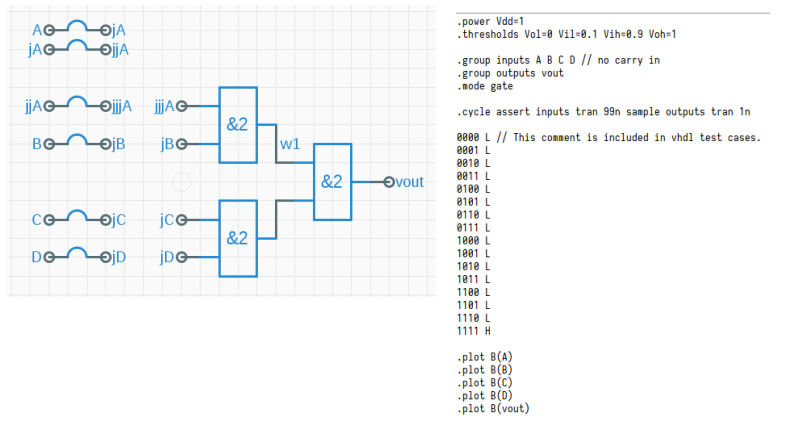
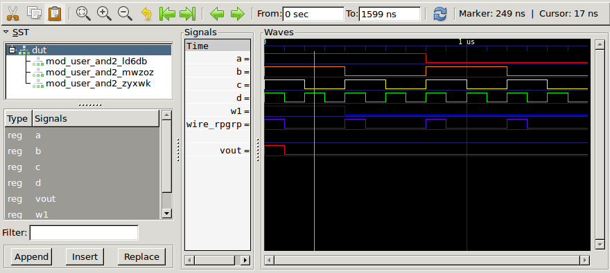
Generates the following VHDL, minus the prelude and a slew of tests. But the tests are passing
entity mod_user_Jumper41 IS
  port (A : in std_logic; B : in std_logic; C : in std_logic; D : in std_logic; vout : out std_logic);
end mod_user_Jumper41;

architecture struct of mod_user_Jumper41 is
  -- node declarations
  signal w1, wire_RPgRp : std_logic;
begin
  -- each submodule is wired up here.
  mod_user_AND2_MwZoZ : entity work.mod_user_AND2 port map (in1 => A, in2 => B, out1 => w1);
  mod_user_AND2_Ld6DB : entity work.mod_user_AND2 port map (in1 => C, in2 => D, out1 => wire_RPgRp);
  mod_user_AND2_ZYxwK : entity work.mod_user_AND2 port map (in1 => w1, in2 => wire_RPgRp, out1 => vout);


end struct;
-- Combinational testbench. ---------------------------------------
library STD;
use STD.textio.all;                     -- basic I/O
use STD.env.all;
library IEEE;
use IEEE.std_logic_1164.all;            -- basic logic types
use IEEE.std_logic_textio.all;          -- I/O for logic types
use ieee.numeric_std.all;

entity mod_user_Jumper41_tb is end entity mod_user_Jumper41_tb;
architecture behavior of mod_user_Jumper41_tb is

  signal A, B, C, D, vout: std_logic;

begin

  dut : entity work.mod_user_Jumper41 port map (A => A, B => B, C => C, D => D, vout => vout);
  process
  begin
    -------------------------------------------------------
    A <= '1';
    B <= '1';
    C <= '1';
    D <= '1';
    wait for 99.0 ns;

  -- ... more tests
1.9 Finding the Drivers
For any module input, the graph component containing that input must also contain a single driving signal, which in the simplified subset of JADE modules presently under consideration would only include outputs from other modules or module inputs determined by the test script.
Here's a problem, many same type submodules in one schematic aren't distinguishable. That's not a problem, yet, because the terminals of submodules are unique, in that they have unique locations. Also, think about
1.10 Implementing the bottom
Can VHDL AND2 gates use component instantiation? Looks like the answer is: No. So the built-ins will need to be handled differently. Looks like built-in AND2 will look like something like this, and be part of a prelude included in toplevel.vhdl
ENTITY AND2 IS
  PORT (in1 : IN std_logic;
        in2 : IN std_logic;
        out1 : OUT std_logic) ;
END ENTITY AND2 ;
ARCHITECTURE Behavioral OF AND2 IS
BEGIN
  PROCESS IS
  BEGIN
    out1 <= in1 AND in2 ;
  END PROCESS ;
END ARCHITECTURE Behavioral ;
So, declare all the components used in the module up front. Then there is a begin keyword followed by each sub-module. What about replication and wire widths not equal to 1? normalize wires into singles and concat? or match VHDL's bundle convention?
entity RAWR IS
  port ( a : in std_logic;
         b : in std_logic;
         c : out std_logic);
end RAWR;

architecture struct of RAWR is
  -- FOR EACH SUB MODULE TYPE IN THE MODULE
  component AND2 PORT (in1 : IN std_logic;
                       in2 : IN std_logic;
                       out1 : OUT std_logic);
  end component;

begin
  -- FOR EACH SUB MODULE IN THE MODULE
  -- in the graph component containing "in1" which element is the source node?
  -- in the graph component containing "in2" which element is the source node?
  -- in the graph component containing "out1" which element is the target node?
  -- how to name the label unit1?

  unit1 : AND2 port map (in1 => a, in2 => b, out1 => c);

end struct;
Also, would it be better to put all modules in one file or one file per module? BTW,
1.11 Wiring the components
INVENTORY
- Have the inputs/outputs from module test script.
- Have all wires with absolutely located terminals from icon
- Have a graph with all signals
What about jumpers? They will always have a source/target. Worry about jumpers later.
What's left? Have to identify source nodes, these will be the inputs to modules and the right hand sides of concurrent assignments…
waitaminute. What about module instantiation? Shouldn't that be the major form of signal routing?
The low down on VHDL Component Instantiation (pdf)
Forget replication for now. What about simple constants assigned to wires like 0xDEADBEEF'32 ? If that's a signal on a wire, then it can be the only signal associated with that node. Some signals are source signals and some are targets. Looking at input directives from test script will resolve that question.
1.12 Decoding the icon
Need to parse the icon view. Why? to get the locations of the terminals so they can located in the graph for connectivity. OK. Once those are in, they will be something something. ??? terminating connections for either inputs or outputs. There theres the in/out terminal pin too, which, I don't if it's used, and I don't know how to handle it if it is.
So, a new Component constructor, TermC was needed. Why? Port/pins/terminals aren't visible on instantiated modules within schematics, however, an instatiated module is represented in the schematic. To get the locations of those ports, it's necessary to look into the instantiated module's icon where port locations can be found.
The whole thing here is to see signals at points to determine the concurrent assignments in HDL. So these terminating connections are critical.
1.13 Tagging the nodes
There will be anonymous nodes, made from anonymous wire connecting components. A hash of the wire should make a good identifier, no two wires are the same. HUH.
1.14 Generating VHDL for the module /user/AND2
The vhdl-language library used here is working well, haven't run into any show stoppers with it yet. The pretty printer works as expected, it does a fine job. NB: The concurrent assignment shown below "asdf <= something;" is hard coded garbage.
JADE module names have slashes in them, VHDL doesn't like that, so I've had to convert them to something agreeable. Double underscores are OK for now.
ENTITY mod__user__AND2 IS
        PORT (in1 : IN std_logic;
              in2 : IN std_logic;
              out : OUT std_logic) ;
END ENTITY mod__user__AND2 ;
ARCHITECTURE func OF mod__user__AND2 IS
BEGIN
    PROCESS IS
    BEGIN
        asdf <= something ;
    END PROCESS ;
END ARCHITECTURE func ;
Not sure what's going on with the nested BEGIN blocks.
1.15 Generating nodes from wires
Wires! JADE's implementation describes wires as having an origin point <x,y>, a rotation [0, 90, 180, 270] and an offset vector. The rotation is applied to the vector and the result is added to the origin which determines the second point of the wire segment. It's up to the programmer to stitch these segments together and figure out how all the wires connect.
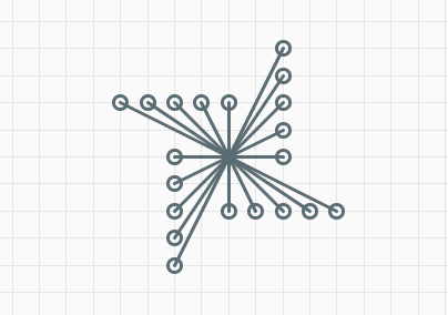
λ> G.components x

fromList [fromList [ (-32,-16),(-24,-16),(-16,-16),6)
                   , (0,0),(0,16),(8,16),(16,-32),(16,-24)
                   , (16,-16),(16,-8),(16,0),(16,16),(24,16)
                   , (32,16)]]

λ> DS.size $ G.components x
1

λ>
This means that all of the above wires are now considered one node.
1.16 Top Down?
A simple module with a simple test .. an AND gate. This will require parsing the JADE test
1.17 Testing MathJax
\(f(x)=x\)